# ESRI shapefile support
SBMT has limited support for loading and saving structures in the [ESRI shapefile format](https://en.wikipedia.org/wiki/Shapefile). While SBMT currently distinguishes between five types of structures ([paths](paths), [polygons](polygons), [circles](circles), [ellipses](ellipses), and [points](points)) shapefiles use a more basic set of primitives (e.g. [LineString, Point](https://en.wikipedia.org/wiki/Shapefile)), and only one type of geometry primitive can be stored in a single shapefile.
Reference: SBMT structures, shapefile-naming convention, and exported attributes
Each type of SBMT structure can be exported from its respective tab in the Structures toolbox panel. Click the Save as... and select ESRI Shapefile Datastore. Shapefile geometry is written in Lon/Lat coordinates with a WGS84 coordinate reference system.
# TODO: The relationship between "paths.shp" and "paths-ctrlpts.shp" is going to change!!!
| SBMT Structure | ESRI Primitive | Control Points Filename | Lon/Lat Geometry Filename | Geometric Attributes |
|--- |--- |--- |--- |--- |
| Points | Point | -- | filename.points.shp | -- |
| Paths | MultiLineString | filename.paths-ctrlpts.shp | filename.paths.shp | -- |
| Polygons | MultiLineString | filename.polygons-ctrlpts.shp | filename.polygons.shp | -- |
| Circles | MultiLineString | -- | filename.circles.shp | center, radius, flattening, angle |
| Ellipses | MultiLineString | -- | filename.ellipses.shp | center, radius, flattening, angle |
# Points
TODO
# Circles and Ellipses
TODO
# Paths and Polygons
Because SBMT represents paths and polygons internally using two levels of granularity (control points and fine geometry) it writes out __two__ separate shapefiles for these structure types. This allows shapefile users to
- load highly-detailed surface-conforming SBMT paths and polygons into applications such as ArcGIS, and
- load and edit control points in a GIS application and re-import the control points into SBMT.
Shapefiles containing path and polygon fine geometry, e.g. paths.shp and polygons.shp, are ignored by SBMT; __only paths-ctrlpts.shp and polygons-ctrlpts.shp can be imported by SBMT__. This is an important distinction, as SBMT is not designed to import structures with hundreds or thousands of segments.
Rather, __SBMT expects just a few control points to be specified__, from which it maps the implied paths and polygons in finer detail on the fly. This can lead to problems when importing large simple polygons from GIS applications into SBMT, as described below.
### Exporting from SBMT
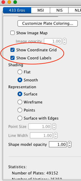
As a first example, we will draw a path on the Eros shape model and export it and view it in a freely-available external GIS tool. Let's start by enabling the coordinate grid and labels in the 433 Eros tab
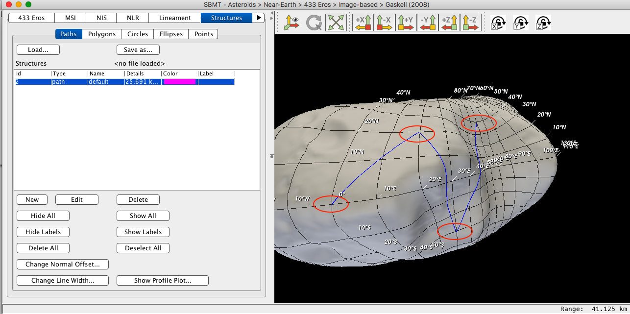
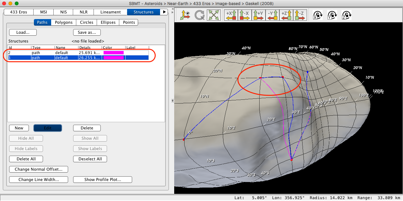
Go to the Structures tab, select Paths, and draw a path on the body. Note the lon/lat coordinates of each control point, which have been circled in the image below.
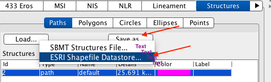
Click Save as... / ESRI Shapefile Datastore..., enter a filename prefix e.g. "myDataStore", and save.
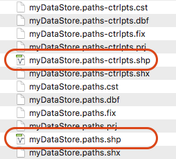
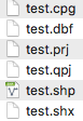
Numerous files will be generated, including two .shp files:
These datastores can be read into the freely available [QGIS3](https://www.qgis.org/en/site/) application. After downloading, installing, and starting QGIS3, click "Datasource Manager"
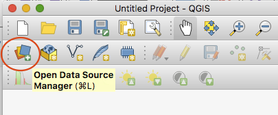
and browse to the SBMT-generated shapefiles:

Double click myDataStore.paths.shp close the Datasource Manager; the path should now be visible in the main QGIS3 window. Enable the grid by clicking "View" / "Decorations" / "Grid"
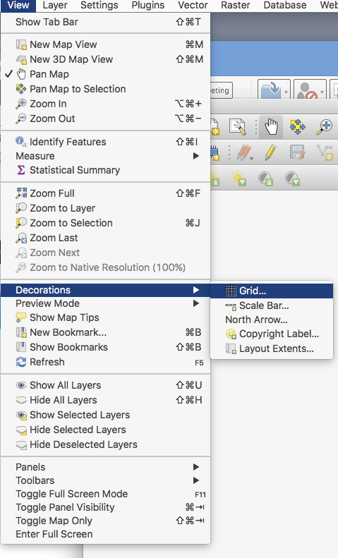
and then click "Enable grid" and "Draw annotation" in the dialog that pops up.
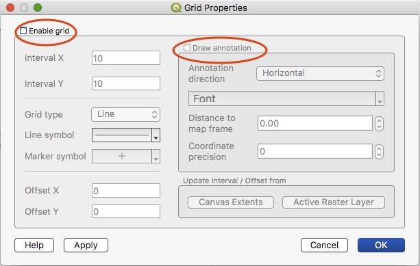
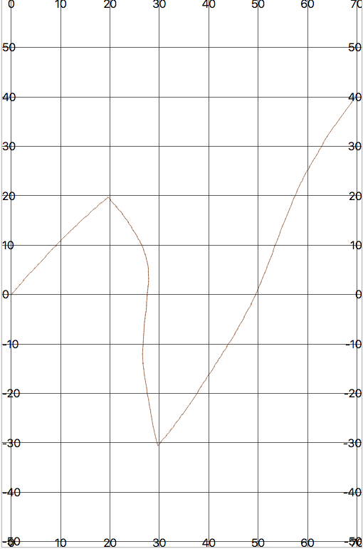
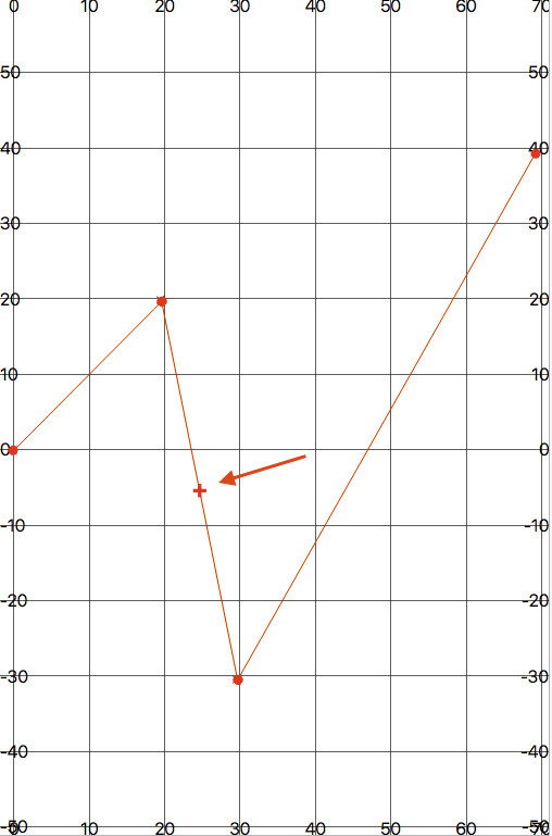
Note how the path curves across the surface, with vertices at the exact lon/lat as shown in SBMT above. The coordinates of each control point are roughly (0,0)-(20,20)-(30,-30)-(70,40).
Reopen the datasource manager and double-click myDataStore.paths-ctrlpts.shp. Unlike the more detailed "paths.shp" file there is no interpolating geometry in the control-points file; QGIS3 simply connects the handful of control points with straight (lon/lat-space) lines.
### Re-importing from an external tool
Now we will edit the control points and import the result back into SBMT. Discard the current work by clicking "New Project", then reload myDataStore.paths-ctrlpts.shp and re-enable the grid. Click "Select features", click on the lines representing the control points in the main window, "Toggle editing" on, and then enable the "Vertex Tool".
 New Project
 Select Features
 Toggle Editing
 Vertex Tool
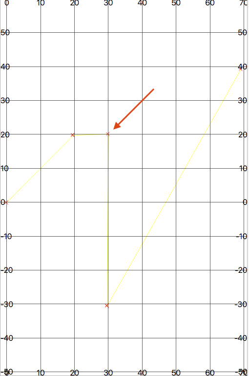
Hover over the midpoint of one of the segments, double-click the red "plus" icon,
drag it to a new location, and double-click again.
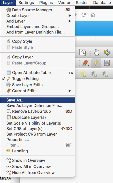
Save the newly edited control points to a shape file. Click "Layer" / "Save as..."
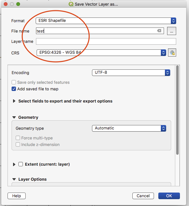
and choose a filename, e.g. "test".
The exported file structure should look something like this:
Finally, back in the Paths panel on the Structures tab click Load... / ESRI Shapefile Datastore and browse to and open test.shp. An error message will pop up regarding the SBMT shapefile naming convention,
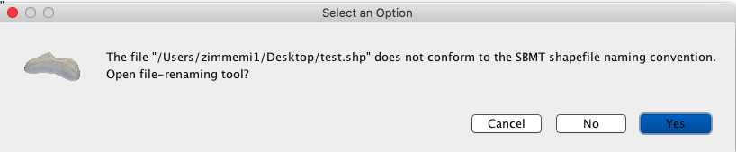
Click "Yes" to open the renaming tool, leave "test" as the file prefix, and select "Paths" as the file content type.
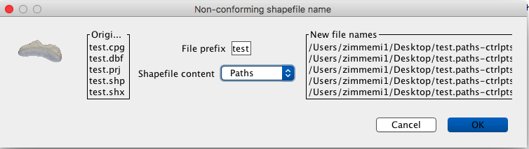
Click "OK" and the files will be renamed accordingly on disk:
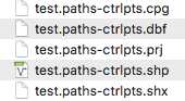
The path should now be visible in the SBMT main window. Note the presence of the newly created (QGIS3) control point, while the fine-grained geometry connecting it to its neighbors has been generated by SBMT on the fly.
### Importing externally-generated shapes
#### Sensitivity to vertex density
Recall that SBMT interprets paths (e.g. "LineStrings" in the ESRI nomenclature) as a set of control points on the body which are connected by a geodesic comprised of finer segments. Tightly-packed control points (relative to the local shape-model radius-of-curvature) tend to result in "straighter" geodesics, while sparse control points lead to "curved" geodesics. This is an extremely important caveat to be aware of when importing shapes from an external GIS tool into SBMT: the mapped path can be very sensitive to vertex density.
Let's test this sensitivity. Here are two polygons created in QGIS3; both are 60 degrees tall and wide, but the left one has four vertices while the right one has roughly ten times as many.
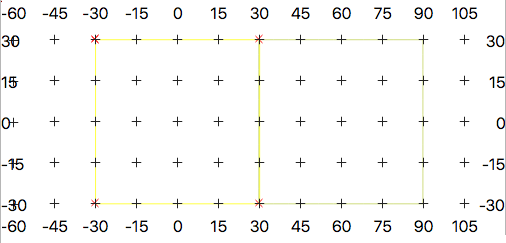Low-res polygon (left, 4 verts)
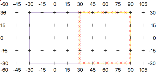High-res polygon(right, ~40 verts)
Exporting to a shapefile, importing into SBMT (using the Eros shape model), enabling the coordinate grid and labels, and dialing down the opacity of the body yields something like this:
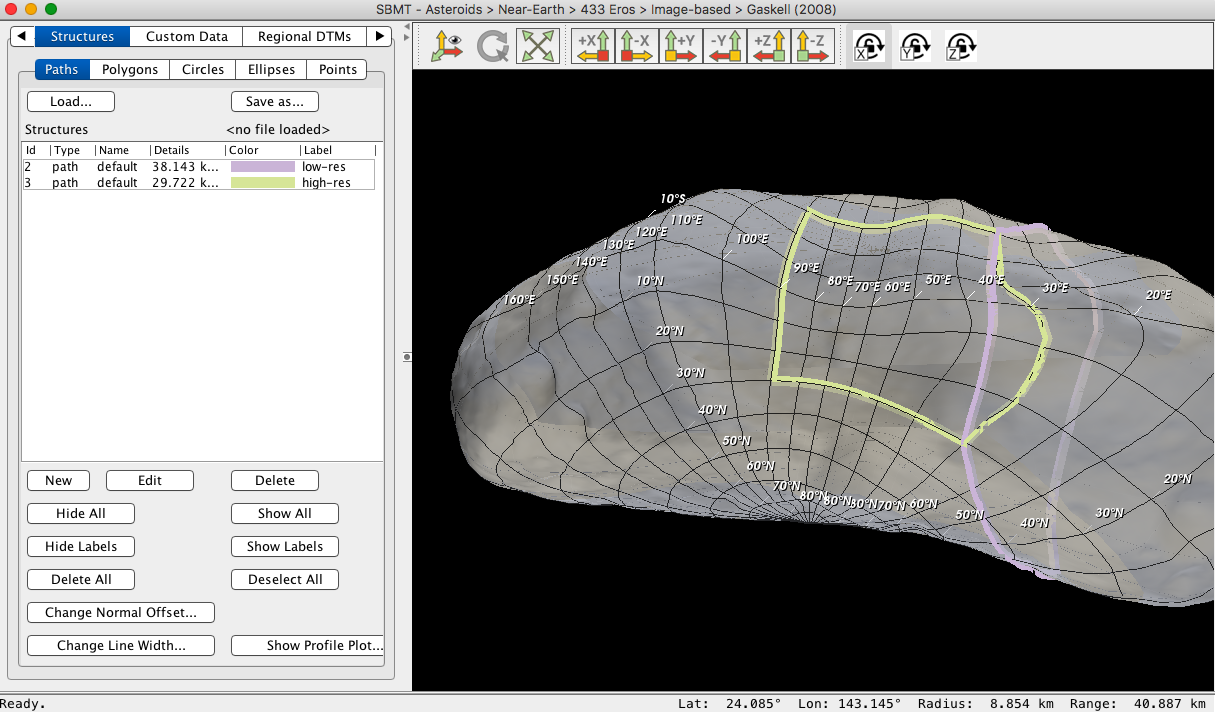
Note how the sides of the high-resolution square map precisely (at +/30° latitude, +30/-90° longitude) from QGIS3 to SBMT; they follow the contours of the shape-model surface along the respective graticules. The low-resolution square does *not* follow its own respective graticules in SBMT. Its four corner vertices (at +/30° latitude and longitude) are mapped accurately onto Eros graticules, but the geodesics in between deviate considerably. This is especially noticeable along the common edge of the two polygons (on the 30°E meridian), where one would naively expect the SBMT-mapped paths to coincide exactly.
#### Further explanation
SBMT's sensitivity to shapefile vertex density is a side-effect of its path-mapping algorithm. This is, roughly:
1. Find the unique plane containing the origin and two adjacent control points.
2. Slice the shape model with this plane to get a segmented line (in 3D space) that conforms to the body.
3. Throw away any parts that lie "outside" the control points.
The resulting polyline represents one possible definition of a "geodesic".
It is crucial to remember that __shapefile vertices are interpreted by SBMT as control points__. If the distance between consecutive vertices (in the plane containing the origin and the vertices) is greater than the local radius of curvature then the resulting geodesic will tend to deviate from the original 2D lat-lon representation. This is the case for the low-resolution polygon shown above.
#### Proposed solution
When reading in a ".paths-ctrlpts.shp" file SBMT knows these are control points. No pre-processing is needed.
When reading a ".paths.shp" file SBMT will give the user a choice of tolerance, probably defined by the dimensionless product __κL__ where __κ__ is curvature and __L__ is distance between control points. Then the segments on file will be decimated/refined to roughly match this ratio all along each geodesic.